Intellibot
Intellibot is a Robotic Process Automation (RPA) platform designed to streamline the life-cycle of RPA implementations at any point of the process.
Below I will explain my experience and project with intellibot.
For this task I used a software called Intellibot. My idea for this task was to go on youtube and search for a youtube channel and watch one of the videos. In order for this to work, I had used the “ActionSet”, “StartApp” and “SetText” actions. Each action plays a massive role.
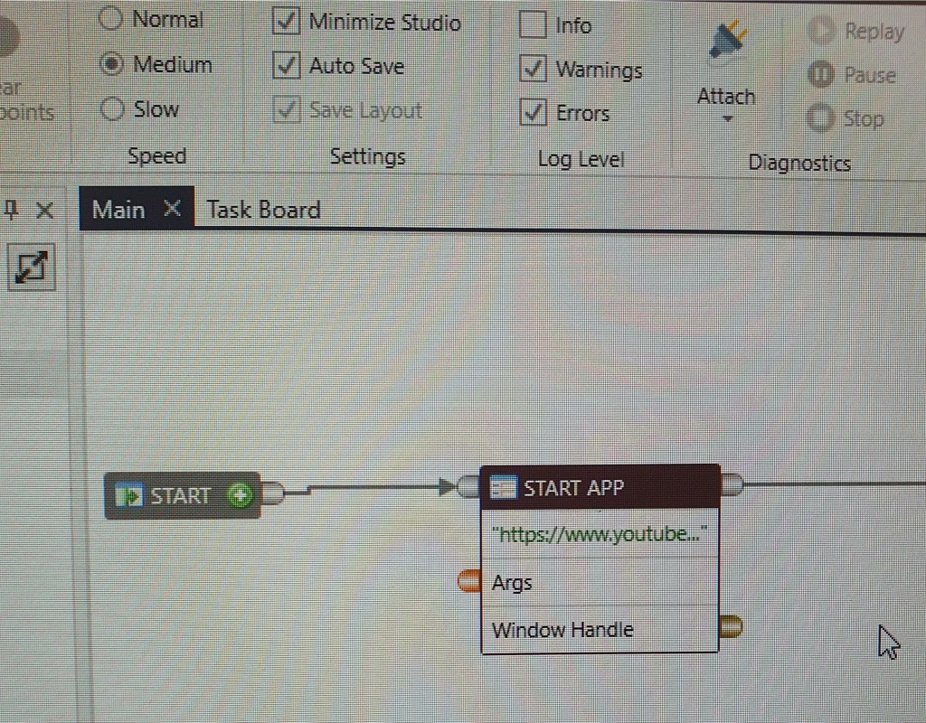
A “startApp” enables the bot to open a website through a browser. In the image below you can see the command. You insert the link where you want the bot to navigate to.
An “ActionSet” allows you to use multiple actions in one, for example you can click and set text. This allows the bot to navigate easily thorough a web by clicking on an area and then typing on the search bar, then clicking the search icon. This is shown in the image below as “Dropz” was typed up by the bot and then searched for on Youtube.

An “SetText” is an action that allows the bot to search a specific thing, in my case I made it search for “Dropz” on YouTube. You can see this in the image below.
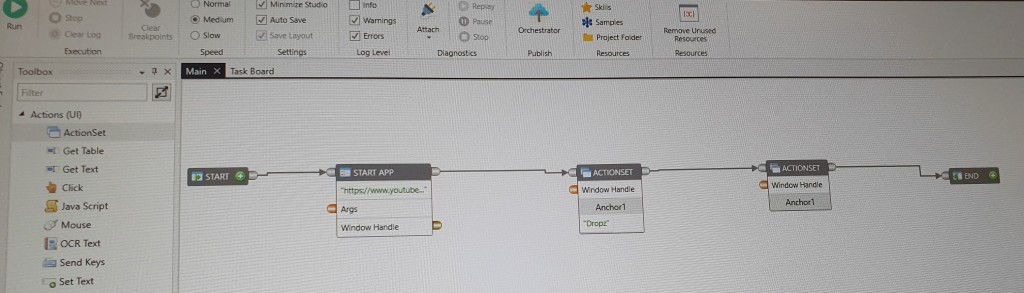
First of all I used the StartApp to command the bot to open up YouTube on a web browser and then I used the “SetText” action to allow the bot to search for “Dropz” on the YouTube search bar. After, I used the “Click” action to command the bot to click the search button and click one of the videos which Dropz has to offer. In the video below you can see the whole process.
Evaluation
Overall, I think that my intellibot project went well. Because it was easy to work on the software and I had no issues what so ever, therefore not needing to modify the script within the software which I’ve tested. Furthermore, the design of the system looked very simple and straight forward, and after I finished putting the system together it was decently responsive when doing the actions, like typing or pressing. However, I think that my commands were to simple and easy, I would of liked to add more actions and make my project more complex, but I didn’t know how to at that time. If there was anything that I would of liked to do different it would be using the “GetImage” action. The “GetImage” action copies an image that you’ve selected.
Arduino
Arduino is an hardware and software company that designs and manufactures single-board microcontrollers for building digital devices.
Below I will explain my experience and project with Arduino.
I decided to do “CIRC02: 8 LED Fun”, as it looked pretty easy and fun. The components I needed were: x8 5mm green LED, x8 560 Ohm resistor, breadboard wiring bundle and microcontroller.
A green LED is a light source which lights on and off when currents flows through it.

560 Ohm resistor limits the flow of electric current through the microcontroller. There are different types of resistors, you look at the colours on it to realise how much Ohm they have, for example the one I used was green, blue and brown which means that it had 560 Ohm.

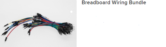
Wires are used to allow electricity to flow from on area to another.
Microcontrollers is a type of computer in a form of an integrated circuit. This is where you connect all the other components to in order for them to function. It has built in I/O capabilities, therefore ti can read and write digital and analog values.

Next, I’ll show and explain you the process I went through in order to complete the Arduino task.
Steps:
- First I had to gather all the components which I mentioned above.
- Then, I had to connect the 8 green LEDs to the circuit (space them out evenly).
- After, I connected the longer side of the green LED to a digital pin on the microcontroller (Start with the 2nd pin and make your way up to the 9th pin).
- Then, I had to connect the 8 (560 Ohm) resistors to the shorter side of the green LEDs.
- Lastly, I connect the USB cable from the PC to the microcontroller.
- Then, I had to copy a script from the internet and paste it in a software called “Arduino IDE” in order for the green LEDs to work (turn on and off). https://learn.adafruit.com/experimenters-guide-for-metro/proj04-code

In the link above you can see the script.
In the video below you can see the final outcome.
Evaluation
Overall, I struggled a bit at the start when making the microcontroller, as it didn’t work the 1st time I tried and all the cables with the other parts made it look confusing and complicated. However, I then found out the issue, which was the green LEDs being placed the wrong way around in the pins. After I successfully made the microcontroller work, the performance of the system was very good, as it was very responsive and accurate. After, I had to add another sensor to the microcontroller, but unfortunately it didn’t work when I added the other sensor which was “CIRC01: Blinking LED”. I couldn’t make both of the sensors work at the same time, which you can see in the video below. Below you will also see the steps and equipment needed for the “CIRC01: Blinking LED”. Next time I do this I would like to make both sensor work at the same time. Also, I would like to add a switch, so that I could control the LEDs when pressing the switch.
Equipment:
- 10mm Blue LED

- 560 Ohm Resistor

- Breadboard Wiring Bundle

- Microcontroller

Steps:
- Firstly, I had to connect the longer leg of the LED to the 13th pin on the microcontroller.
- Then, connect one leg of the 560 Ohm resistor to the shorter leg of the resistor, and the other leg of this resistor should be connected to the rail with the black wire.
- Lastly, I had to copy a script from the internet and paste it in a software called “Arduino IDE” in order for the blue LED to work (turn on and off).
In the link below you can find the script.
https://learn.adafruit.com/experimenters-guide-for-metro/circ01-code%20
